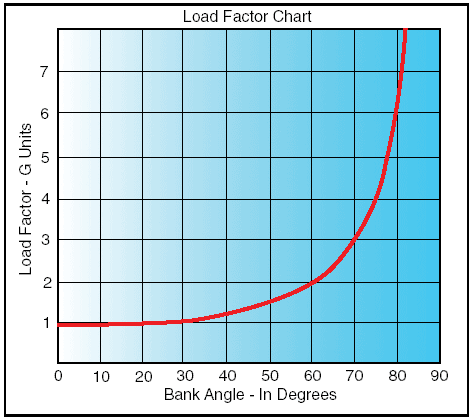
How To Read A Load Factor Chart
When this table is used it results in an occupant load for which a room space and building is designed to. The operating flight strength limitations of an airplane are presented in the form of a V-n or V-g diagram.

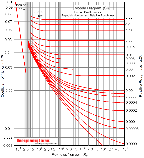
Moody Diagram Adapted From Streeter V L Et Al 1985 With Permission Chemical Engineering Rough Flow
Once the occupant load is established the means of egress is then designed for at.
How to read a load factor chart. Factor 10 1015 1154 1414 2000 2923 5747 11473 Load factor cha 0 10 20 30 40 50 60 70 80 90 Bank angle in degrees FIGURE 2Load Factor Chart. The load factor and in particular its sign depends not only on the forces acting on the aircraft but also on the orientation of its vertical axis. To the limit loads given above a safety factor of 50 percent is added.
Use a load chart. By referring to the load chart a crane operator can determine what angle the boom will have to be to ensure that he or she is directly above the load. Depending on the specific type of crane you are using this piece of equipment may come with a convenient load chart which will allow you to estimate the.
Table 100412 displays the occupant load factor based on the function or use of a space or room. 28 20 14. L design floor live load.
HC Lifting height multiplied by the capacity. Less maximum demand can be catered by a low capacity power plant. Load factor in many classic texts is labeled n but have become G in keeping with pilot phraseology.
Duct and register. If you do not have a load chart you can calculate the sling load factor using the ratio of the sling length divided by the sling height. Equipment selection and sizing 3.
For this example we will use a sling length of 28 feet and a height of 20 feet. D estimated mean dead weight of the construction. As we talk about being LEVEL in.
Per person a m. Fig-ure 2 shows that power factor tends to drop off sooner but less steeply than efficiency as load decreases. Put your presentation title or confidentiality info here.
L r maximum roof live load anticipated. Utility mild acrobatics including spins 44 to 176. 1The load combinations and factors are intended to apply to nominal design loads defined as follows.
During straight and level flight the load factor is 1 if the aircraft is flown the right way up 2. H design lateral pressure for soil conditiontype. A gross factor is applied to the entire floor area including the area occupied by interior walls corridors columns fixed furnishings shafts and the like.
As Load Factor Average Load Maximum Demand. For airplanes with gross weight of more than 4000 pounds the limit load factor is reduced. R Radius between the ground and load.
The distance is measured from the center pin of the crane to the center of the load. The occupant load factor is based on function. Normal 38 to 152.
1 Vertical Stress in a Soil Mass Forces that Increase Vertical Stress in Soil Mass Weight of soil effective stress Surface loads Fill large area Point loads. Use of Grab Hook without cradle or supporting wings reduces the WLL of. This chart is usually included in the aircraft flight handbook in the section dealing with operating limitations.
Figure 1 Motor Part-Load Efficiency as a Function of Full-Load Efficiency 0-1hp 15-5hp 15-25 hp 75-100hp 10hp 30-60hp Efficiency PercentFullLoad. How is occupant load determined when a building has. Indicates the sling angle is equal to twice the greatest angle of inclination of a leg to the vertical.
A net factor is applied only to the floor area available for use excluding the aforementioned areas. Combined all safety factors for a grossly exaggerated load. Hydro pole light stand column etc Lines loads Rack or rail loading strip foundation Rectangular area Raft or rectangular footing Circular area tank Earth embankment Road railway fill ice etc.
Live Load Factor 175 β 25 Operating Level Live Load Factor 135 LRFR LOAD FACTORS FOR HL-93 LOAD FACTORS FOR LEGAL LOADS TRAFFIC VOLUME LOAD FACTOR ADTT 5000 180 ADTT 1000 165 ADTT 100 140 For ADTT between 100 and 5000 interpolate the load factor. Table 7312 Occupant Load Factor Use ft. We can write it for a period of T hrs as below Load Factor Average Load xT Maximum Demand xT.
Reading the Load Charts. Indicates nip angle which must not exceed 120. Units generated in T hrs Maximum Demand xT.
Acrobatic 60 to 30. Here youd graph out the specific lift the crane is needed for. Thus a higher value of load factor means less maximum demand.
In this case the sling load factor would be. 40 37 Sales area on floor below street floor. Put your presentation title or confidentiality info here.
You need to lift a load of 15 tons 30000 pounds a distance of 25 feet. Before lifting a load with a crane the operator must check the boom angle indicator which will provide the angle of the boom from horizontal. The ft indicator on the left axis represents the radius the distance from the center pin to the center of the load.
Underloaded when it is in the range where efficiency drops significantly with decreasing load. In mercantile occupancies 300 279 In other than storage and mercantile occupancies 500 465. 30 28 Sales area on two or more street floors.
90 whereas it becomes 1. Note that it is NOT based on the occupancy group classification. If the load cells reading is 27 millivolts 0027-volts and the load cells maximum sensing weight is 100 pounds this multiplication will yield 27 volt-pounds.
Step 2 Multiply the load cells reading in millivolts by the full scale weight of the load cell. This is an aircraft load factor graph demonstrating how G loading or G-forces occur on the aircraft and in turn you when making level turns level turns being holding a constant altitude and not climbing or descending. Sales area on street floor.
Indicates that WLL applies to both rectangular and circular load.

Tire Pressure Chart Tyre Size Wheels And Tires Car Care
:max_bytes(150000):strip_icc()/dotdash_Final_Peak_and_Trough_Analysis_Dec_2020-01-9b55fbfeaeec49909c57199b43f7adb7.jpg)
Peak And Trough Analysis
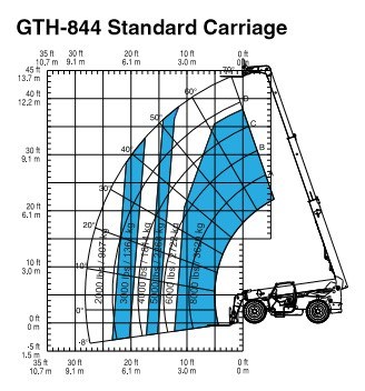
Interpreting A Telehandler S Load Charts
Load Factors

Structural Steel T Beam Dimensions In 2021 Steel Beams Beams H Beam Sizes
Moody Diagram

Pin On Hoisting
Posting Komentar untuk "How To Read A Load Factor Chart"